
I²C is a phillips inter-intergrated circuit, a multi master serial bus that uses two wires (plus pwr & ground)
The beauty of I²C is that we can connect multiple devices using only two pins, Serial Clock and Serial Data. In the case of the Raspberry Pi, this helps immensely as GPIO is a limited resource.
For example, using an MCP23017 I/O Expander, we can use just two lines on the Pi and at the same time add 16 extra GPIO pins to our project. Multiple I²C devices can be added to the bus.
To get started with I²C on a Raspberry Pi, it must first be enabled. Here’s how you do it…
Remove I²C from the blacklist
By default, I²C is disabled on a RPi, to enable it you can use the following commands:
cp /etc/modprobe.d/raspi-blacklist.conf /etc/modprobe.d/raspi-blacklist.conf.i2ctmp
cat /etc/modprobe.d/raspi-blacklist.conf.i2ctmp | sed -r ‘s/^[ ]*blacklist i2c-bcm2708/#blacklist i2c-bcm2708/i’ > /etc/modprobe.d/raspi-blacklist.conf
Install i2c-dev
We’ll need to load the i2c-dev kernel module, lets install that now
apt-get install i2c-dev && echo “i2c-dev” >> /etc/modules
And we’re done, probably best to give your RPi a reboot.
Testing it out
With the I²C kernel module loaded, open up a terminal session and lets scan the I²C bus by issuing the i2cdetect command
sudo i2cdetect -y 1
What you’re presented with is a current view of the i2c bus, it should look like this
     0  1  2  3  4  5  6  7  8  9  a  b  c  d  e  f
00: -- -- -- -- -- -- -- -- -- -- -- -- --
10: -- -- -- -- -- -- -- -- -- -- -- -- -- -- -- --
20: -- -- -- -- -- -- -- -- -- -- -- -- -- -- -- --
30: -- -- -- -- -- -- -- -- -- -- -- -- -- -- -- --
40: -- -- -- -- -- -- -- -- -- -- -- -- -- -- -- --
50: -- -- -- -- -- -- -- -- -- -- -- -- -- -- -- --
60: -- -- -- -- -- -- -- -- -- -- -- -- -- -- -- --
70: -- -- -- -- -- -- -- --
Here we can see the address table for the bus, currently there is nothing attached. Now I’ll attach an MCP23017 I/O expander to my Rasbperry Pi’s Clock and Data along with power and ground.
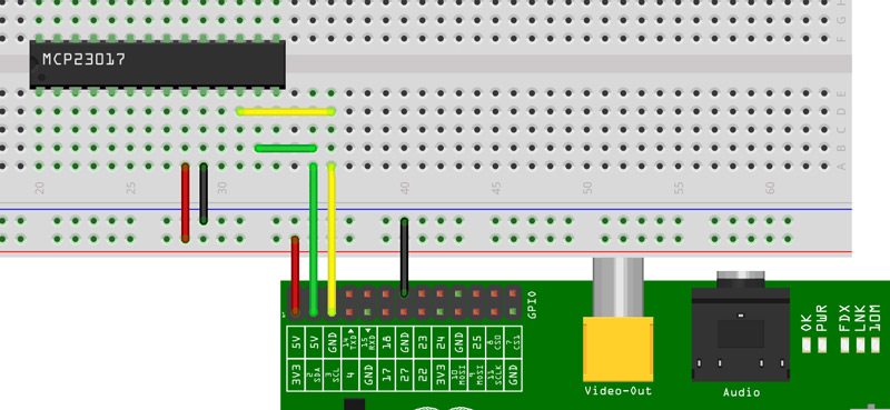
Note that the breadboard diagram does not show pins 15,16 & 17 being tied to GND (setting the I²C address) but I’ll cover the MCP in more detail in another post.
Now when I boot my RPi and run i2cdetect…
     0  1  2  3  4  5  6  7  8  9  a  b  c  d  e  f
00: -- -- -- -- -- -- -- -- -- -- -- -- --
10: -- -- -- -- -- -- -- -- -- -- -- -- -- -- -- --
20: 20 -- -- -- -- -- -- -- -- -- -- -- -- -- -- --
30: -- -- -- -- -- -- -- -- -- -- -- -- -- -- -- --
40: -- -- -- -- -- -- -- -- -- -- -- -- -- -- -- --
50: -- -- -- -- -- -- -- -- -- -- -- -- -- -- -- --
60: -- -- -- -- -- -- -- -- -- -- -- -- -- -- -- --
70: -- -- -- -- -- -- -- --
Here we can see we have a device at 0×20. Now you’ll probably want to read Talking I²C with Python