
So we’re all agreed that the Raspberry Pi is pretty ninja right? A credit card sized computer for less than 30 quid? Where’s the catch? Well there is a catch, to keep that price point as low as possible the RPi is missing a few bells and whistles, one of those being the RTC or Real Time Clock.
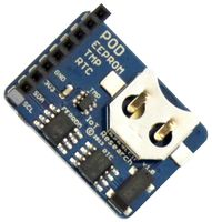
This is what keeps your computers time when it’s powered off and whilst it’s missing from the RPi, a true ninja will add their own. For one particular project I worked on, an RTC was critical and the ability to monitor case temperature was also a nice to have. That’s when I stumbled upon the RASPI-Pod from Ciseco. This small, stackable breakout board comes in a variety of flavours, here we’re using the B025 model that provides an RTC, a Texas Instruments TMP100 temperature sensor and a small amount of EEPROM.
Let’s get started…
Before we start, you’ll need to have read this article on enabling I²C for your Raspberry Pi. Now that’s out of the way, lets take a quick look at the hardware…
Ciseco RASPIPod
So there’s not much to see here. A coin battery holder keeps the RTC powered when your RPi is powered off. Simply provide 3.3v and GND to the marked pins and hook up the SDA (Serial Data) and SCL (Serial Clock) lines to your RPi Clock and Data lines. That’s a very simple process so I’m not going to put that in pictures here.
If you’re new to I²C you’ll probably want to have a read of Talking I²C with Python before digging in here.
Now we’re going to jump into some command line stuff, in this example we have nothing else connected to the I²C bus.
If you’ve read my previous posts on I²C, you’ll be familiar with the commands we’re about to run so bring up a terminal session and run
i2cdetect -y 1
What we’re presented with is this
     0  1  2  3  4  5  6  7  8  9  a  b  c  d  e  f
00: -- -- -- -- -- -- -- -- -- -- -- -- --
10: -- -- -- -- -- -- -- -- -- -- -- -- -- -- -- --
20: -- -- -- -- -- -- -- -- -- -- -- -- -- -- -- --
30: -- -- -- -- -- -- -- -- -- -- -- -- -- -- -- --
40: -- -- -- -- -- -- -- -- -- -- 48 -- -- -- -- --
50: 50 -- -- -- -- -- -- -- -- -- -- -- -- -- -- --
60: -- -- -- -- -- -- -- -- -- -- 68 -- -- -- -- --
70: -- -- -- -- -- -- -- --
This tells me that on the bus is the RTC at 0×68, the Temperature sensor at 0×48 and EEPROM at 0×50. How do I know this? Because I read the documentation for the pod ![]()
We’re actually not going to do anything with the EEPROM, we’re going to focus on the RTC and the temperature sensor.
Setting up the RTC
We don’t really want to interact with the RTC ourselves, we could do but it’d be much nicer if the system interacted with the RTC instead. Although the RTC chip is manufactured by Texas Instruments, we’ll be using the Dallas instruments DS1307 RTC kernel driver so let’s make sure that gets loaded at boot time
echo “rtc-ds1307″ >> /etc/modules
We also need to ensure the device is created at boot so add the following to /etc/rc.local (before exit 0).
echo “ds1307 0×68″ > /sys/class/i2c-adapter/i2c-1/new_device
hwclock -s
When we reboot and scan the i2c bus again, all being well we should see
     0  1  2  3  4  5  6  7  8  9  a  b  c  d  e  f
00: -- -- -- -- -- -- -- -- -- -- -- -- --
10: -- -- -- -- -- -- -- -- -- -- -- -- -- -- -- --
20: -- -- -- -- -- -- -- -- -- -- -- -- -- -- -- --
30: -- -- -- -- -- -- -- -- -- -- -- -- -- -- -- --
40: -- -- -- -- -- -- -- -- -- -- 48 -- -- -- -- --
50: 50 -- -- -- -- -- -- -- -- -- -- -- -- -- -- --
60: -- -- -- -- -- -- -- -- -- -- UU -- -- -- -- --
70: -- -- -- -- -- -- -- --
Note how 0×68 is now reporting UU, this is exactly what we want as it indicated that the address is in use, now set the clock to the correct time.
hwclock –set –date=”2014-04-14 06:00:12″ –utc
Now, shutdown your RPi and leave it powered off for a while before booting it back up (without a network connection to avoid NTP setting the date/time). Now when you check the system date/time it should be correct as the RTC has kept the time whilst there was no power to the RPi.
Setting up the Temperature Sensor
As I’ve mentioned countless times, I²C required only two wires so we’re already hooked up to the temperature sensor. From here it’s just code and again, this kind of thing requires time spent in data sheets but to get you going, here is some sample code to query the TMP100 chip for the current temperature.
import smbus
ADDR = 0×50;
REG_CONFIG = 0×01;
REG_TEMP = 0×00;
REG_TEMP_L = 0×02;
REG_TEMP_H = 0×03;
CFG_RESOLUTION = 0x9F;CFG_RES_12BIT = 0×60;
CFG_CLEAR = 0xFE;
CFG_SHUTDOWN = 0×01;bus = smbus.SMBus(1);
# read config register
cfg = bus.read_byte_data(ADDR,REG_CONFIG);# specify 12bit resolution
cfg = cfg & CFG_RESOLUTION
cfg = cfg | CFG_RES_12BIT
bus.write_byte_data(ADDR,REG_CONFIG,cfg);# now read the temp
temp = bus.read_word_data(ADDR,REG_TEMP)# some bit manipulation is required now read the datasheet!
degreesC = (val&0xFF) + ((val>>12)/16.0);
print degreesC + ‘c’;
Now when we run the python we get back the current temperature ![]() I guess I ought to have gone into a little more detail on using the TMP100 but I’ll leave it as an excersize for the reader… again, read the data sheet
I guess I ought to have gone into a little more detail on using the TMP100 but I’ll leave it as an excersize for the reader… again, read the data sheet