
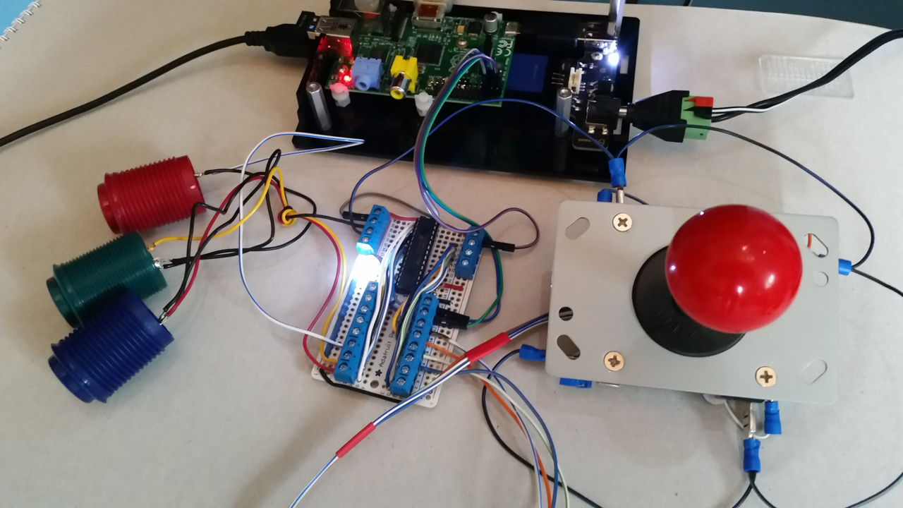
Here’s how I constructed the joystick interface board. It’s pretty simple, a 28pin DIL socket an a heap of screw terminals and a few trace wires.
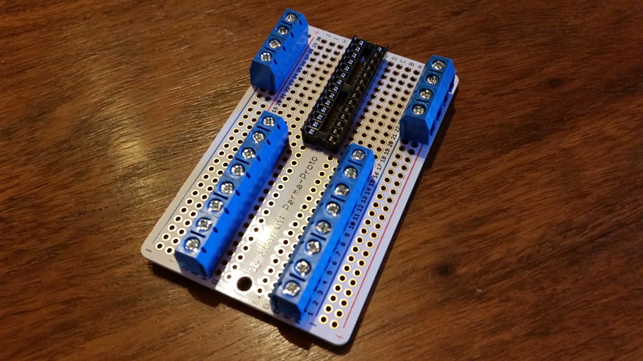
Components positioned
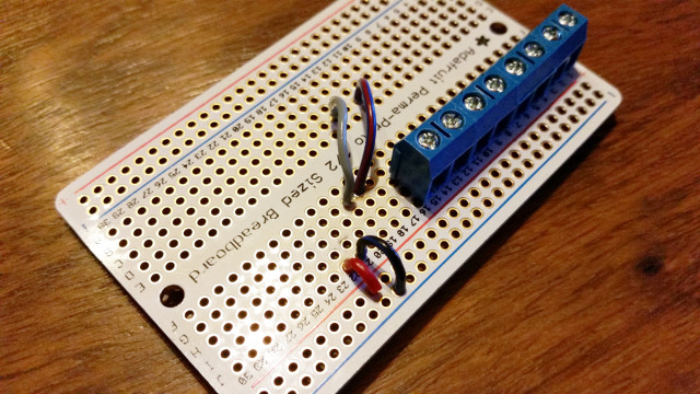
Breaking out the IC
Left side of the IC complete
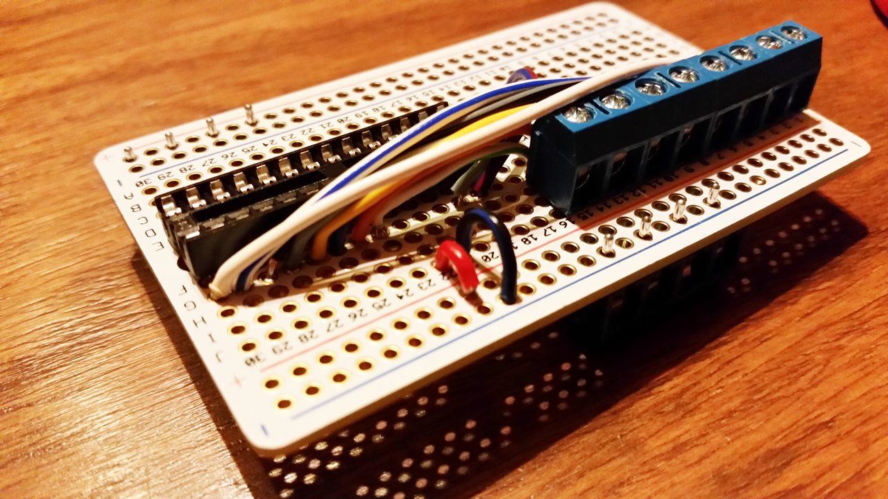
Almost there
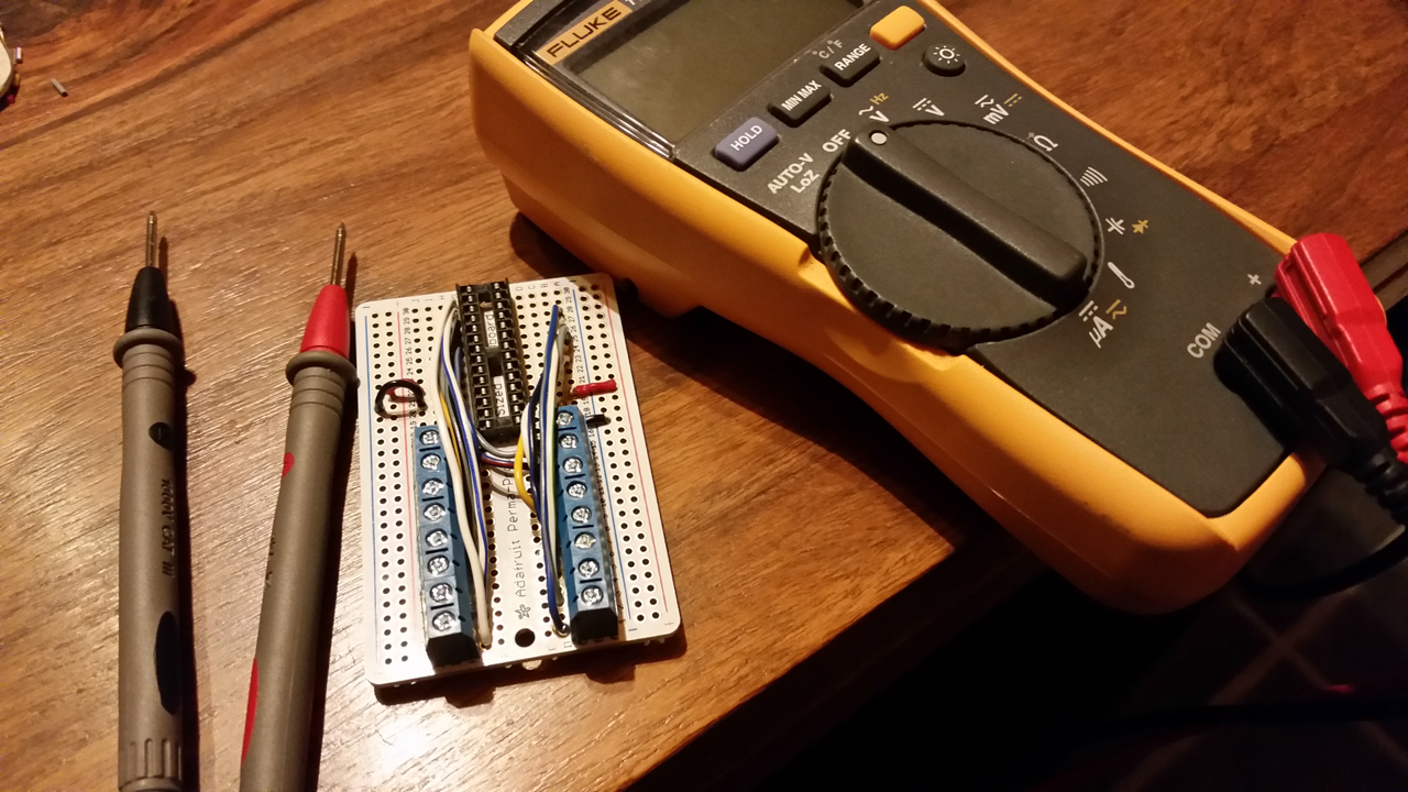
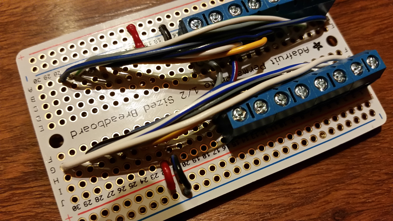
Checking all of the connections
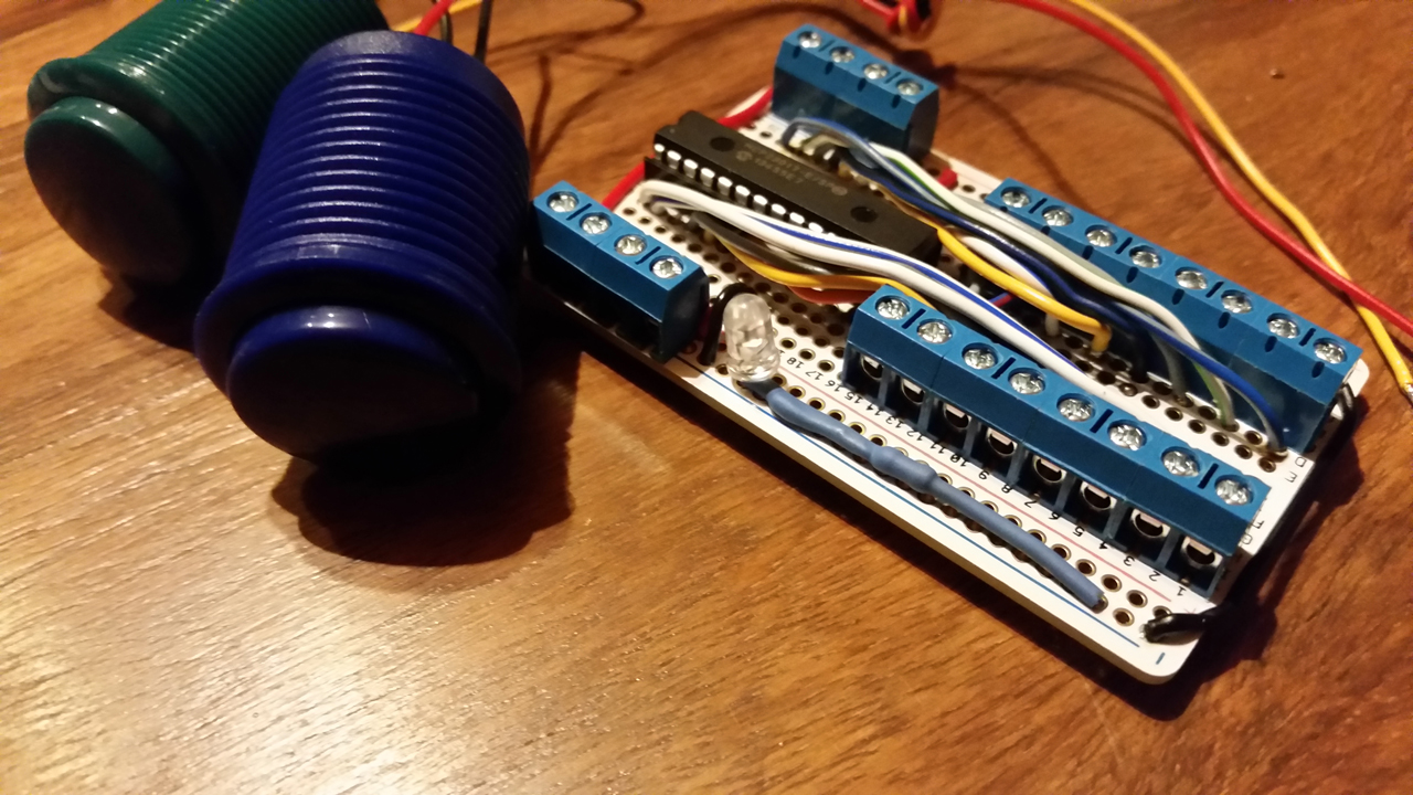
Added a ninja LED
Some final checks
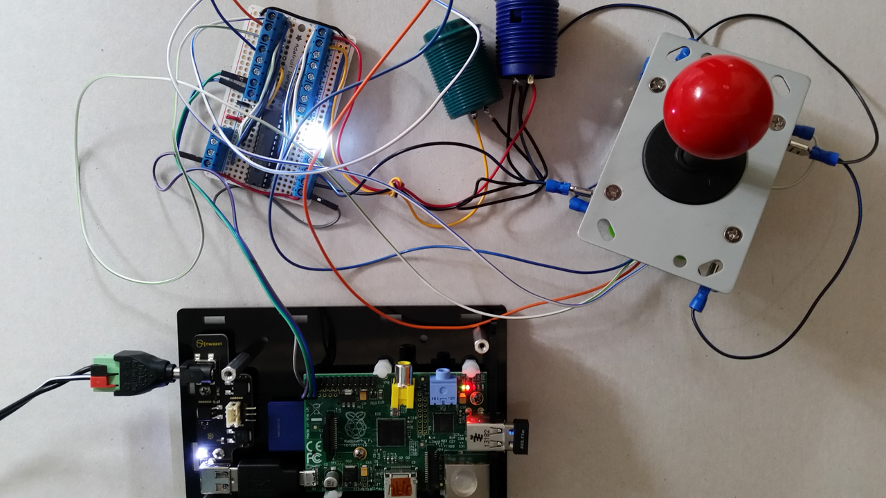
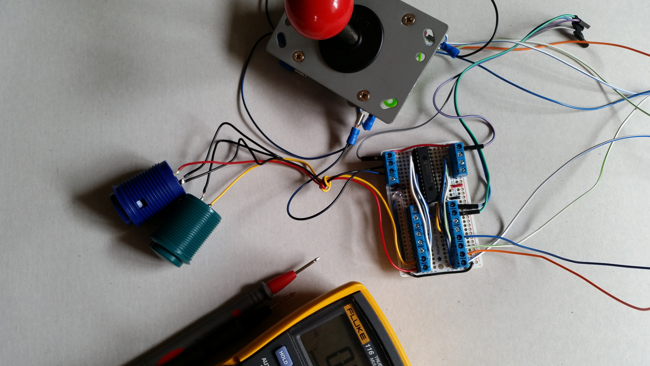
Hooked up and ready to go
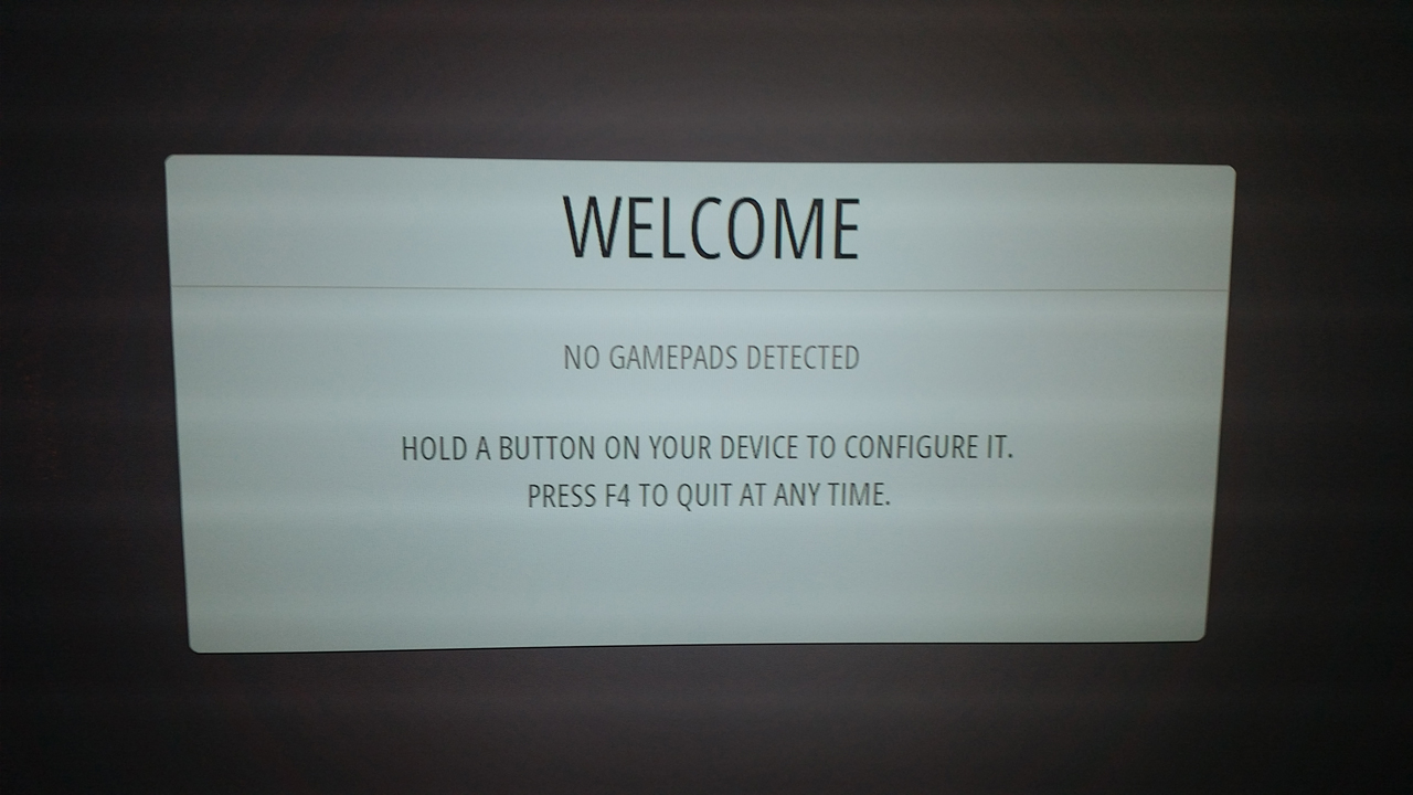
Fail
Looks like I fogot to comile the joystick kernel driver!
apt-get update
apt-get install -y --force-yes dkms cpp-4.7 gcc-4.7 git joystick i2c-tools

wget http://www.niksula.hut.fi/~mhiienka/Rpi/linux-headers-rpi/linux-headers-`uname -r`_`uname -r`-2_armhf.deb
dpkg -i linux-headers-`uname -r`_`uname -r`-2_armhf.deb
rm linux-headers-`uname -r`_`uname -r`-2_armhf.deb

wget https://github.com/digitalLumberjack/mk_arcade_joystick_rpi/releases/download/0.1.0/mk-arcade-joystick-rpi-0.1.0.deb
sudo dpkg -i mk-arcade-joystick-rpi-0.1.0.deb
Now I should be able to load the kernel driver using 0×20 as that’s my controller address
mk_arcade_joystick_rpi map=1,0x20
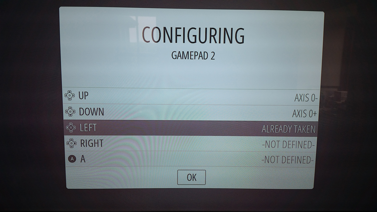
Win
Less spaghetti
That was pretty easy. Had I purchased the right screw terminals life would have been a lot easier as way less wiring would have been involved.
I’ll also need to change the resistor on that LED to stop it from literally setting your retinas on fire any time you want to look at the connections.
I’ll need to repeat the process for a second joystick which makes this a prime candidate for a proper PCB. Here’s one I made in fritzing that can handle a pair of joysticks.
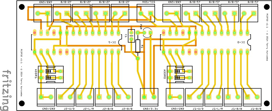
Twin joystick interface
Pingback: Making an I²C Joystick interface | Slinky Ninjas Projects